Systa Bus Component
The systa_bus Component provides status reading connectivity to solar heat energy collector controllers using the Systa Bus
protocol.
Supported Models
Section titled “Supported Models”The following table shows the currently supported models of SystaSolar devices.
Supported Models
Section titled “Supported Models”| Name | Config Value |
|---|---|
| PARADIGMA SystaSolar Aqua | systasolar_aqua |
The Config Value should be used for the model parameter in your sensor and text_sensor entries.
Hardware Connection
Section titled “Hardware Connection”The device must be connected via a UART bus supporting the receiving line only. The UART bus must be configured at 9600bps. The controller outputs data depending on the packet type up to multiple times per second.
To convert the signal on the bus to UART that can be received by the ESPHome device, a converter circuit is needed. This circuit must apply a lowpass filter to the signal and convert the voltage to a safe level for the ESPHome device.
The following circuit uses simple components and provides electrical isolation between the bus and the ESP.
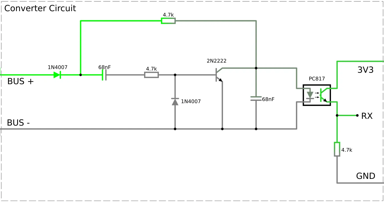
An alternative circuit design can be found here.
Component
Section titled “Component”# Example configuration entrysysta_bus: uart_id: systa_uartWARNING
If you are using the Logger make sure you are not using the same pins for it or otherwise disable the UART
logging with the baud_rate: 0 option.
Configuration variables
Section titled “Configuration variables”- uart_id (Optional, ID): Manually specify the ID of the UART hub used to connect to the device.
NOTE
Functionality of the sensors depends on the type of the device and the scheme arrangement of the hydraulic system it controls. The actual arrangement number set up can be determined from the settings of the device. Please check the user manual and assess your arrangement to determine the functionality of each sensor and name them accordingly.
Sensor
Section titled “Sensor”# Example configuration entrysensor: - platform: systa_bus model: systasolar_aqua temperature_tsa: name: Temperature TSA temperature_tse: name: Temperature TSE temperature_twu: name: Temperature TWU temperature_tw2: name: Temperature TW2 pump_speed: name: Pump SpeedConfiguration variables
Section titled “Configuration variables”- model (Required): Specify the model of the connected controller. Choose one of the config values listed in the table of supported models above.
Supported sensors:
- for systasolar_aqua:
temperature_tsa,temperature_tse,temperature_twu,temperature_tw2,pump_speed.
All sensors are Optional and support all other options from Sensor.
NOTE
Sensors are updated every time a data packet is sent by the device. Some models send data very often, possibly every second. If you are
concerned about the load on the receiving database, you can add a throttle filter to the sensors.
Text Sensor
Section titled “Text Sensor”# Example configuration entrytext_sensor: - platform: systa_bus model: systasolar_aqua error_code: name: Error CodeConfiguration variables
Section titled “Configuration variables”- model (Required): Specify the model of the connected controller. Choose one of the config values listed in the table of supported models above.
Supported text sensors:
systasolar_aqua:error_code.
All text sensors are Optional and support all other options from Text Sensor.